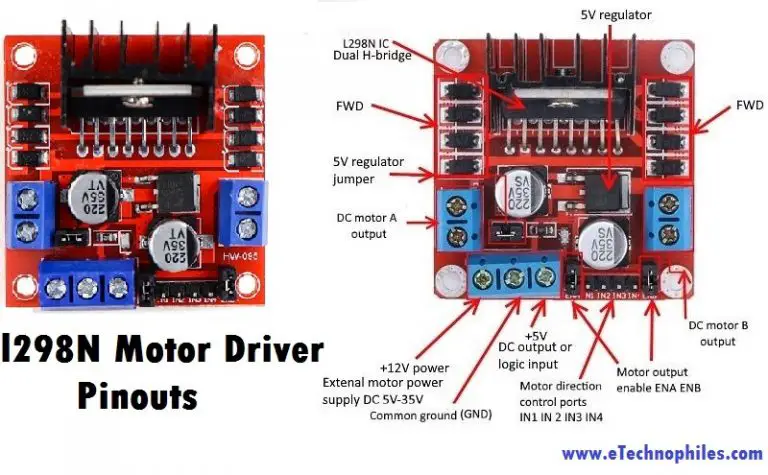

If you want to supply more than 12V, remove the jumper and connect 5V to the +5V connector. When the jumper is in place, however, the chip is powered by the motor’s power source, so you don’t have to give 5V through the +5V terminal. The L298N chip is powered by the +5V connector. The motors are powered by the +12V terminal block.

OUT1 and OUT2 at the left and OUT3 and OUT4 at the right.Ī three-terminal block containing +12V, GND, and +5V is located at the bottom.

The motor driver has a two-terminal block on each side for each motor. Let’s take a look at the L298N motor driver pinout and see how it works. Additionally, it allows us to drive two DC motors simultaneously, which is perfect to build a robot. We’re going to use the L298N motor driver that can handle up to 3A at 35V. The method we’ll use here is suitable for most hobbyist motors, that require 6V or 12V to operate. There are many ways to control a DC motor. Power source: 4x 1.5 AA batteries or Bench power supply.The module can drive DC motors that have voltages between 5 and 35V, with a peak current up to 2A.


 0 kommentar(er)
